2 Fitting BBC BASIC
The job of fitting the BBC BASIC board in
the ATOM requires removal and replacement of the bottom case
section, plugging and unplugging ICs, plugging in the board
itself, and one or more soldered joints. Users without
constructional experience should refer the task to an Acorn
dealer.
The BBC BASIC board fits on Side Two (the
component side) of the ATOM board. It plugs into four of the
existing IC sockets, which give it access to power and the
necessary signals, and one flying lead connects to a pad on the
ATOM board. To allow BBC and ATOM modes to be selected from the
keyboard, three more flying leads must be connected. Whether
these are used or not, the main procedure is as follows:
- Remove the bottom section of the ATOM
case by turning the ATOM upside-down, unscrewing the two
screws, and lifting off the bottom.
Locate LK2 in the top left-hand corner of the ATOM board,
next to the 6522 VIA, viewing the board with the keyboard
section at the bottom. Make a link at this point with a
short length of wire. The joints can be soldered on the
component side with a bit of care.
This link allows the 6522 VIA to generate interrupt
requests, used by the additional MOS to implement ESC and
the TIME and SOUND features.
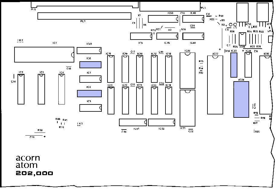
- Three ICs must be removed from the
ATOM board and two of these transferred to the BBC BASIC
board. If a Utility ROM is fitted, this must also be
transferred. The BBC BASIC board plugs into the sockets
left empty. Using Figures 1 and 2 to locate the positions
of the ICs on the ATOM and BBC boards, transfer them
one-by-one according to the following table:
| Position on ATOM board |
IC6 |
IC8 |
IC23 |
IC24 |
| Position on BBC board |
IC9 |
IC15 |
- |
IC4 |
| IC type |
74LS
138 |
74LS
00 |
74LS
138 |
Utility
ROM |
To remove an IC, carefully prise it
out of its socket with a small screwdriver, or use an IC
removal tool if available. when replacing an IC make sure
all the pins are accurately positioned over their
separate sockets before pressing home. All ICs have a
polarising mark on their top surface, either a depressed
dot to one side or a half moon shape. This must be next
to the half moon shape marked in white on the board for
the unit to work. Figure 2 shows the correct orientation
of the ICs transferred to the BBC BASIC board.
- The BBC BASIC board should now be
fitted by plugging the pins that extend downwards from
the non-component side into the sockets on the ATOM board
left empty by the last stage. Figure 2 shows where it
sits in relation to the other components on the ATOM
board. The top-right hand corner of the BBC BASIC board
goes under the fold of the heatsink on the main board, so
the right-hand end should be pushed home first, checking
that the pins at both ends are positioned correctly. The
unit may fail to work if any pin is not plugged in, so be
careful not to bend any while inserting the board, and
check for a stable fit before going on to the next stage.
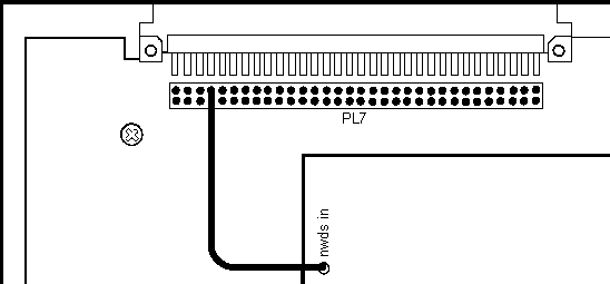
- Take the end of the wire connected to
the point marked 'nwds’ near the top left-hand
corner of the BBC BASIC board, and solder it to the
fourth pad from the left in the top row of the group of
pads marked PL7 in the top left-hand corner of the ATOM
board, as shown in Figure 3. If the bus expansion
connector is already fitted in this position, the
connection will have to be made on the other side of the
board.
- If keyboard selection of ATOM BASIC
and BBC BASIC is required, follow (a) below; otherwise
follow (b).
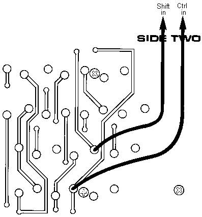
a) The three wires connected to the BBC BASIC hoard at
the right-hand end of the top edge must be soldered to
pads in the keyboard section of the ATOM board. Connect
the two outside wires, marked 'ctrl in' and 'shift in',
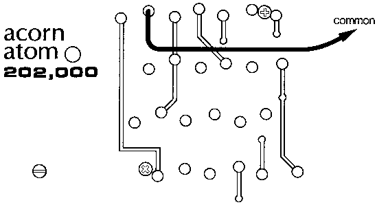
as shown in Figure 3, and the centre wire as shown in
Figure 4. Figures 3 and 4 show details of the right and
left-hand ends of the ATOM board respectively.
(b) Solder a wire link joining the two left-most holes of
the group of four holes marked LK1, near the top edge of
the BBC BASIC board. This selects BBC BASIC, and it can
be fitted across the other two holes instead to return to
ATOM BASIC.
- Finally, check that all the these
steps have been carried out correctly, and then replace
the bottom case section and screws
Power-up the ATOM and press BREAK. If the
link described in 6(b) link has been fitted, the ATOM will start
up in the selected mode. ATOM BASIC starts up with its usual
message, and BBC BASIC displays this:
BBC BASIC
>
If the keyboard mode-select option is being
used, pressing BREAK with either the CTRL or one of the SHIFT
keys held down will select BBC or ATOM BASIC respectively.
Pressing BREAK alone resets the ATOM without changing mode.
Figure 1: Atom
motherboard with chips to be removed highlighted
Figure 2: Conversion
card fitted into Atom, with chips to be fitted highlighted
Figure 3: Connection to
the Shift and Ctrl keys
Figure 4: Connection to
the Common keyboard signal
Figure 5: Connection to
the nwds signal
Next
Chapter
|