- a coded instruction,
- part of the address of some other part of memory, or
- some actual data which is used in the course of the processing.
Once the PEEKO – Computer and all its features have been mastered it is quite an easy step to write machine code programs in 6502 code, opening up a whole new range of fast – action applications for the ATOM
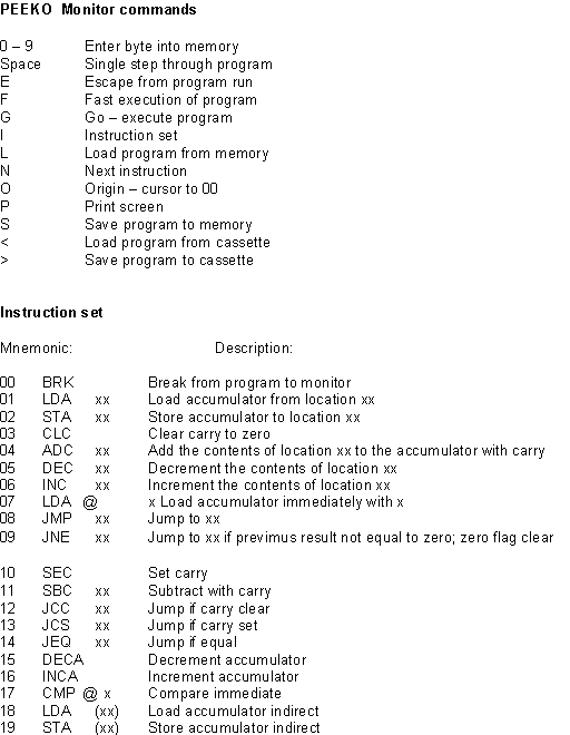
PEEKO – Computer MonitorWhen PEEKO is RUN the user enters the ‘monitor’ of the PEEKO – computer. The monitor commands are single keystrokes:
| 0 – 9 | Pressing any digit key will modify the contents of the memory location indicated by the cursor; the cursor then moves on to the next location. The monitor replies with a bleep to show that it has accepted the data, thus making it easy to enter programs without looking at the display. The mnemonic of each instruction being entered is shown as it is built up, with the format of any arguments expected. |
| G (GO) | Causes the PEEKO – computer to execute the program in its memory, starting at location zero. The program will continue to run until it meets a BRK instruction, or the user presses E (escape). |
| F (FAST) | Similar to C, but the program runs faster. |
| E (ESCAPE) | In RUN mode S stops the execution of the program and returns to READY mode. |
| SPACE | Allows the program to be executed one step at a time. By repeatedly pressing space successive instructions are executed, and the mnemonic for each instruction is displayed. |
The ATOM’s usual cursor controls can be used to move the cursor around.
| O (ORIGIN) | Moves the cursor back to memory location zero. |
| S (SAVE) | Allows programs to be saved in the ATOM’s graphics memory. The S is followed by a single digit, 0 – 9, which identifies the program. If only 3K of graphics memory is present only 0 to 3 should be used. |
| L (LOAD) | Followed by a single digit, it allows the corresponding program to be loaded from the ATOM’s memory into the PEEKO – computer. |
| I | Allows the instruction set of the PEEKO – computer to be changed. In addition to the 10 standard instructions there is a second set of 10 instructions, any of which can be substituted for any of the standard ones. In this mode entering S will return the PEEKO – computer to its standard instruction set. |
| P (PRINT) | Dumps the program in the PEEKO – computer onto a printer. The dump will be printed in double – width characters on an Acorn 02 – 80; for other printers modifications to lines 9400 to 9410 may be necessary. |
| N (NEXT) | Steps through the program, an instruction at a time, displaying each mnemonic – |
| > | Saves the program, and the current instruction set, onto cassette. It will first prompt for a filename. |
| < | This will load a program and instruction set from cassette having first prompted for the filename. |
What do microprocessors do?
- A microprocessor uses a number of memory ‘locations’, each of which contains a ‘byte’. In the PEEKO – computer each byte is a single decimal digit.
- Each memory location has a unique ‘address On the PEEKO – computer the address consists of two decimal digits; reading left to right, row by row, the addresses are 00, 01, 02 ……… 48, 49.
- The byte at each location can represent either:
- an ‘instruction’, On the PEEKO – conputer there are ten different instructions, 0 to 9;
- part of an address – two bytes are required to specify an address;
- some ‘data’ which the processor can use and/or modify during the course of its program.
- The processor itself contains ‘registers’ which it may use during the course of a progran. The PEEKO – computer has only one – the ‘accumulator’
- Some special addresses can be used to pass information to and from the outside world, using the ‘output port’ and ‘input port’. On the PEEKO – computer the input port has address 98 and the output port address 99.
Instructions
Each instruction has a name of three or four letters called the ‘mnemonic’ which describes what the instruction does.
Different instructions require different information following them:
- Some require two bytes to specify the address of the memory location to which the instruction refers. For example, the ‘store accumulator’ instruction, STA, is followed by the address where the byte in the accumulator is to be stored

It is important to note that in the PEEKO – computer the low byte of the address MUST be specified FIRST, although the instruction mnemonic shows the bytes the usual way round. - Some instructions are ‘immediately’ followed by a single byte which is the data to be used by the instruction. For example, the ‘load accumulator immediate’ instruction, LDA @ is followed by the number to be loaded:

- Some instructions do not require any data. For example, the ‘clear carry’ instruction, CLC, simply clears the carry flag to zero:

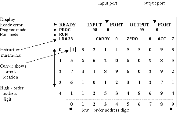
The standard PEEKO – computor instruction set is:
| Mnemonic: | Description: | ||
| 0 | BRK | Break from program to monitor | |
| 1 | LDA | xx | Load accumulator from location xx |
| 2 | STA | xx | Store accumulator to location xx |
| 3 | CLC | Clear carry to zero | |
| 4 | ADC | xx | Add the contents of location xx to the accumulator with carry |
| 5 | DEC | xx | Decrement the contents of location xx |
| 6 | INC | xx | Increment the contents of location xx |
| 7 | LDA@ | x | Load accumulator immediately with x |
| 8 | JMP | xx | Jump to xx |
| 9 | JNE | xx | Jump to xx if previmus result not equal to zero; zero flag clear |
Programs
A ‘program’ consists of a sequence of instructions which the processor executes, instruction by instruction, starting from the lowest address until it reaches a BRK instruction. The ‘jump’ instructions are designed to make the processor leave its normal sequence of execution, and fetch its next instruction from some other specified address.
Programming the PEEKO – Computer
The following section illustrates the use of the PF.EKO computer’s instructions. Most of the instructions will be introduced by means ef a demonstration program. Each program will be shown as a series of mnemonics and their assembled code, and in most cases a printout of the screen.
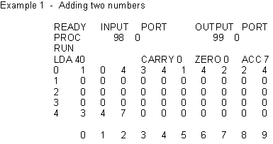

First type in the code starting at location 00. Notice how each instruction is ‘built – up’ on the line below ‘RUN’ on the screen. Next enter the two digits to be added at locations 40 and 41 – use the cursor controls to get the cursor there.
To run the program type space to enter single step mode. Pressing space again executes the first instruction, LDA 40; this loads the contents of location 40 into the accumulator. The next instruction, CLC clears the carry flag to zero. The ADC adds the contents of 41 to the accumulator with the zero carry and puts the result in the accumulator. Next the STA instruction will store the result in location 42. Finally BRK causes the program to stop.
If the numbers chosen added up to 10 or more it will be noticed that 42 only contains the last digit and the carry is set to 1. The next example uses the carry flag to add two two – digit numbers.
By typing C or F from the monitor the program can be run without single stepping.
Example 2 – Add 2 two – digit numbers
This adds the numbers in 40, 41 and 42, 43 and puts the result in 44, 45, 46.
This program contains one new instruction this is LDA @ which loads the accumulator immediately with the next byte in the program – in this case 0.
Problem 1
Using LDA. STA, ADC, CLC and LDA@ write a program that will add the numbers in locations 40, 41 and 42 storing the two digit result in 43 and 44.Example 3 – Countdown program
The following program will subtract one from location 40 each time it goes round a continuous loop. (N.b. 0 – 1 = 9)

This program introduces two new instructions. DEC subtracts one from the specified memory location
- in this case 40
- and JMP causes the program to goto the location specified by the next two bytes like GOTO in BASIC.
By typing F instead of space to run the program PEEKO will execute the program without stopping after each instruction.
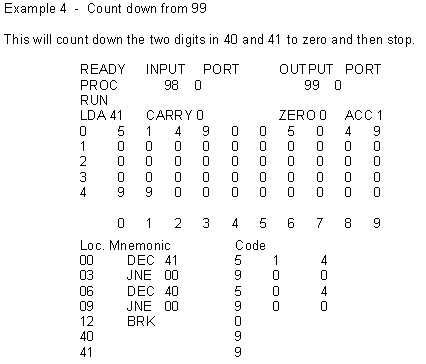
By single stepping through this it will be noticed that when location 41 gets to 0 the zero flag changes from 0 to 1. The zero flag is set whenever an arithmetic instruction gives a zero result, and to 0 otherwise. The JNE instruction is similar to JMP except that the jump only occurs if the previous result was not equal to zero. This causes the program to count down to zero.
The INC instruction is similar to DEC except that it adds one to the following address. It also will set the zero flag if the result is zero, my replacing DEC (code 5) with INC code 6) in the previous program and setting 40 and 41 to 0 the program can be made to count up to (1)00.
Problem 2
Write a program that will count from 99 to 0 and back up to (1)00 in a continuous loop.
Alternative instructions
The instructions discussed so far form the standard instruction set. In addition to these there are 10 alternative instructions which can replace any of the standard instructions. The (i) command in the PEEKO Computer will ask for the number of the instruction to be replaced and the number of the instruction that will take its place. This ability to change the instruction set makes the PEEKO – computer very adaptable and able to be programmed for many tasks despite its limited program size. Most of this secondary set can be explained very easily as they are similar to those in the standard set

The last two extra instructions are an indirect load and store. These are more complex than the others so will be dealt with in greater depth in example 6,
The next 5 programs use some of these features. Before they are typed in the instruction set should be changed to the required set as shown in each example
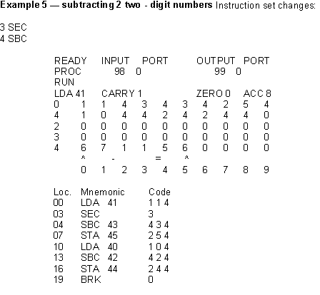
Calculates 40, 41 – 42, 43 with the result in 44, 45. A carry of 1 indicates no overflow. If the carry is 0 then 42, 43 was greater than 40, 41 and hence there is a negative result.
Problem 3
Write a program to multiply two single – digit numbers by successive addition.
Example 6 – Indirect addressing
Instruction set changes:
1 LDA (2 STA ( This program uses indirect addressing. If locations 40 and 41 were: 0 2
and location 20 was: 8
then LDA ( 40 ) would load the accumulator from location 20 (as 40, 41 contains 20) and would therefore be loaded with 8.

By running this short program you will be able to see how indirect addressing can be used to move the contents of one address to another address, in this case from 30 to 20.
Example 7 — Copying a 10—digit table
The program for this example is supplied on cassette, as the file COPY, and can be loaded into the PEEKO – computer using the < command.Instruction set changes:
1 LDA (2 STA (

This example shows how indirect addressing can easily be used to access a table of data. The program will copy a lime of data, starting at the location pointed to by 40, 41, to the location pointed to by 42, 43. Locations 20 to 29 should contain the data to be copied to 30 to 39.
Example 8 – Add two lines of data
This program is supplied on cassette as the file ADD. Instruction set changes:
1 LDA (2 STA (
7 STA
The program will add two lines of data in the memory together, and store the result. As space is limited in the PEEKO computer the program actually adds up two lines within the program itself.
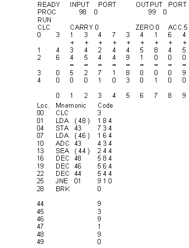
This program again uses indirect addressing extensively.
Example 9 – Finding a factor of a number
This program is supplied on cassette as the file FACTOR.Instruction set changes:
3 SEC
4 SBC
8 JCC
The program finds the highest factor less than 10 of the 2 digit number in 48, 49.
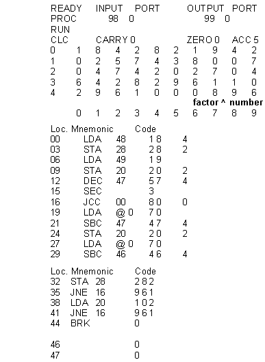
Put the number to be factorised in 48, 49.
Problem 4
Program the PEEKO – computer to divide a 2 digit number by a single digit. This will certainly need SBC and SEC and could also need some other instructions. Take the factor program as an example.
Input and Output Ports
These two ports, at locations 98 and 99 in the PEEKO computer, correspond to the A and B ports of the 6522 VIA chip which can be fitted inside the ATOM. The input port reads in the bottom 4 hits of port A, putting the data in PEEKO location 98. If the Input is larger than 10 it is cut to one digit and the carry flag is set to 1. The output port outputs the data to port B.
Since the printer also uses the 6522 VIA chip for its output, it will be necessary to unplug any I/O devices and plug in the printer if a hard copy of a program using these ports is needed.
Answers to Problems
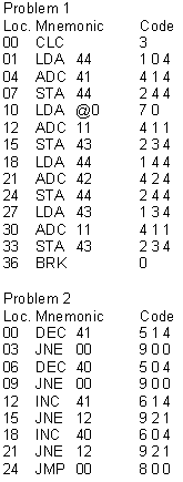
This proqram will count up and down locations 40 and 41. You will probably notice that it does not stop at 00 when counting down, but when it decrements from ten (i.e. 12 11 10 00 01 02 . You should be able to correct this when you have found out about the carry flag and its related conditional jumps later.
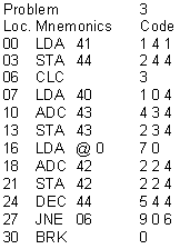
This multiplies the contents of 40 and 41 puttinq the result in 42 and 43.
Problem 4
instruction set changes:3 SEC
4 SBC
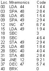
This divides the contents of 44 and 45 by the contents of 46, leaving the result in 47, 48 and 49 are used in the calculation.
